Gearbox Transmission Design
KEY CONNECTIONS
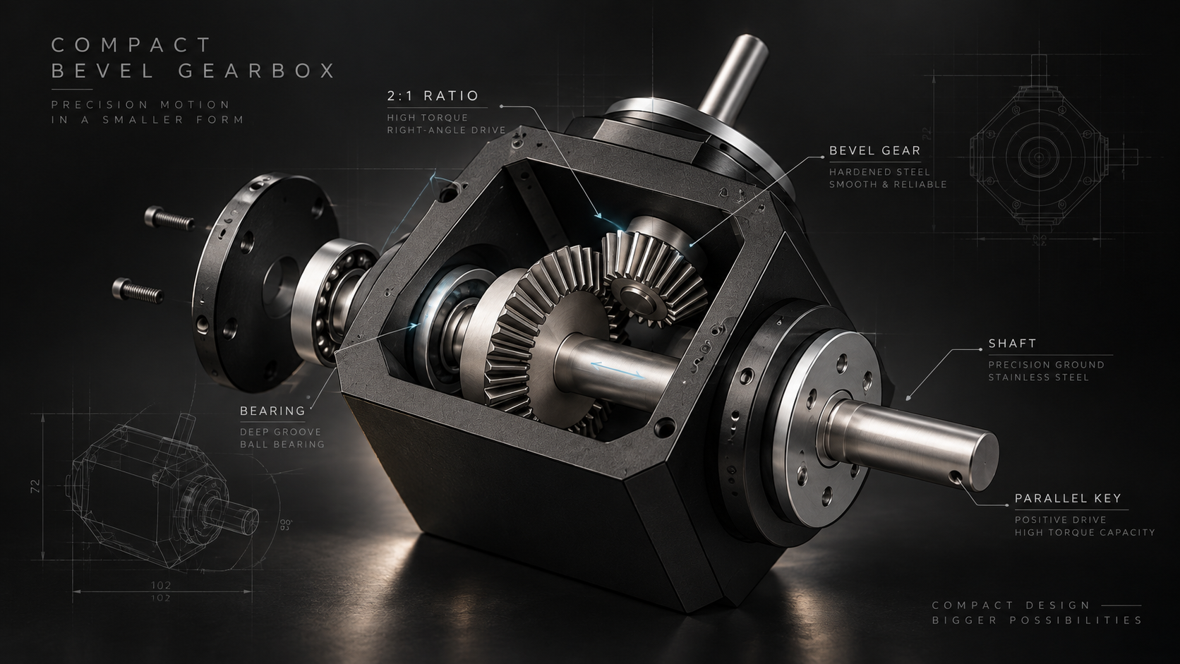
Parallel Key Design
BEARING SELECTION
Static & Dynamic Loads
2:1
Specified Transmission Ratio
SHAFT SUPPORT
Load-Carrying Structure
COMPACT ASSEMBLY
Interference-Free Packaging
ISO 23509
Bevel Gear Geometry
DIN EN ISO 286
Fits & Tolerances
Output Shaft
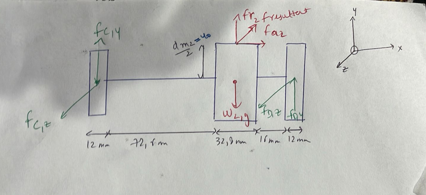
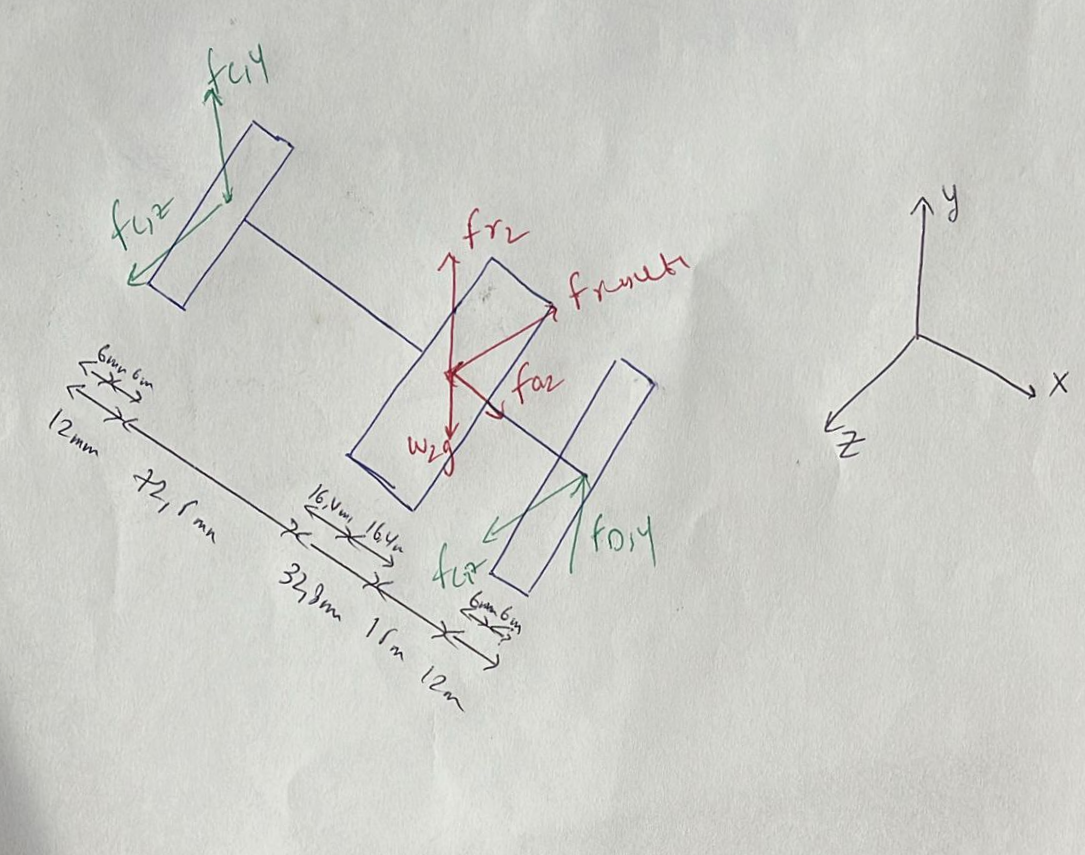
Safe power transmission depends on every component carrying its load correctly.
Gear forces, shaft stresses, bearing loads, keyway connections and assembly clearances were considered together to reduce the risk of mechanical failure.
Tools & Applications
SolidWorks · Siemens NX · MATLAB · ANSYS · Microsoft Excel · Microsoft Word · Microsoft PowerPoint
Input Shaft
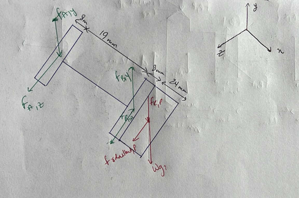
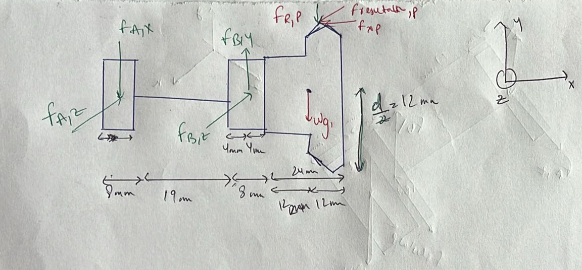
BEARING SYSTEM
Radial & Axial Load Support
GEAR MESH
Defined Transmission Ratio
PARALLEL KEYS
Shaft-to-Hub Connection
ISO 10300
Bevel Gear Load Capacity
Why the Gearbox Was Designed
CONTROLLED TRANSMISSION
A defined gear ratio was required to transfer rotational motion between input and output.
LOAD MANAGEMENT
Torque, radial forces and axial forces had to be understood throughout the complete load path.
SHAFT RELIABILITY
Shafts had to transfer torque while supporting the forces generated by the gear system.
BEARING RELIABILITY
Bearing selection had to consider both static and dynamic operating loads.
CONNECTION INTEGRITY
Parallel key connections were used to create reliable torque transfer between shafts and mounted components.
ASSEMBLY ACCURACY
Mechanical interferences had to be identified and corrected before finalizing the assembly.
COMPONENT INTERACTION
Gear, shaft, bearing and connection design could not be treated independently.
DESIGN VALIDATION
Analytical calculations and CAD were used together to verify the mechanical concept.
ISO 281
Bearing Load Rating & Life
Project Outcome
From calculated loads to a mechanically integrated transmission system.
System Design & Development
CAD + ANALYSIS
SolidWorks · MATLAB
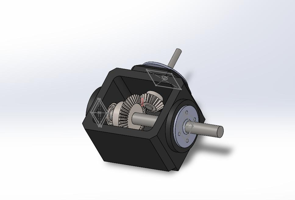
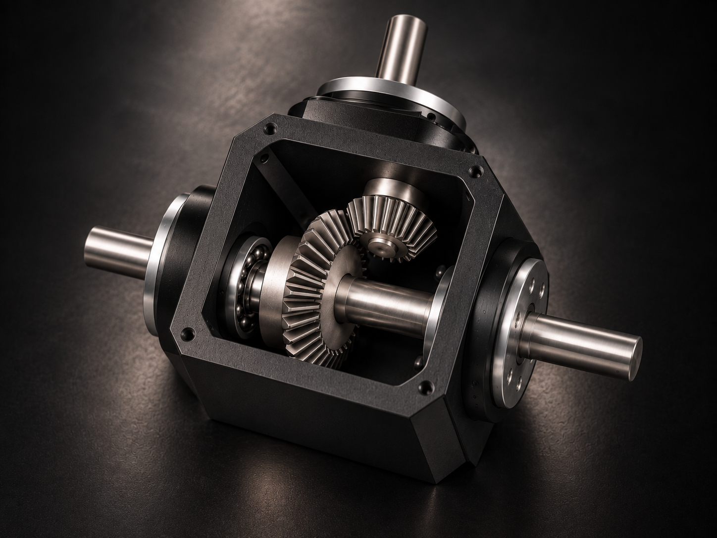
The gearbox was developed as a complete mechanical transmission assembly rather than as individual components. Gear forces were transferred into shaft loads, bearing requirements and shaft-hub connections, while CAD was used to verify the complete arrangement.
DIN 743
Shaft & Axle Strength
DIN 6885
Parallel Keys & Keyways
A gearbox is only reliable when every component in the load path works as one system.
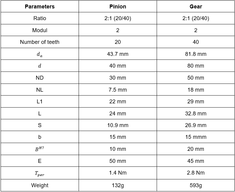
The challenge was to achieve the required 2:1 transmission ratio while ensuring that gears, shafts, bearings and key connections could transfer the acting loads reliably and fit together without mechanical interference.
POWER TRANSMISSION
Controlled Mechanical Transfer
How It Works?
INPUT ROTATION
Power enters through the input shaft
↓
DRIVE GEAR
Input torque is transferred to the gear
↓
GEAR MESH
Forces are transferred between the meshing gears
↓
DRIVEN GEAR
Transmission ratio changes the speed-torque relationship
↓
OUTPUT SHAFT
The resulting torque is transferred through the shaft
↓
BEARING SUPPORT
Radial and axial loads are carried by the bearings
↓
OUTPUT TRANSMISSION
Mechanical power leaves the gearbox